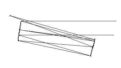
Fig. 1: The ray path of the two-mirror double-pass TCT.
The tilted-component telescope (TCT) is a well-known approach to overcome the drawbacks originating from the central obstruction in conventional reflecting telescopes. In theory the image quality of a TCT can reach the physical limits for a given aperture.
Because a TCT can be made for a fraction of the cost of an apochromatic refractor, a lot of different designs were developed. These range from the single mirror Herschelian telescope to the modern three and four-mirror designs [1-7]. However, none of these telescopes can really compete with the apochromatic refractor especially for compactness.
Every mirror tilt results in additional optical aberrations. To make the telescope diffraction limited, all aberrations have to be compensated in a reasonable field of view. Depending on the particular type of TCT, this compensation leads either to a complicated system with respect to the number of components, or to the type of mirror surfaces (e.g. toroidal), or to an unfavorably long focal ratio of the telescope. In brief, the ideal TCT is an obstruction free, mechanically compact system with two simple mirror surfaces and a fast focal ratio. It should be diffraction limited at least in a half degree field of view. In this article a significant step forward to this goal is presented.
Fig. 1 shows the general scheme of the new TCT design. The first mirror is a convex sphere, the second one is concave. From the optical point of view it is a four-mirror system, i.e., both mirrors are used twice. Due to the double-pass concept, the telescope becomes very compact and exhibits excellent compensation of all optical aberrations.
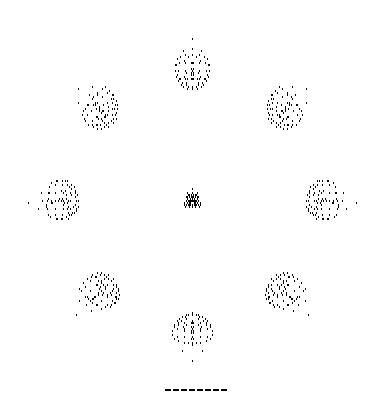
As a first example a system composed of two spherical mirrors with 200mm aperture and 2300mm focal length (focal ratio F/11.5) is discussed. The spot diagrams for a field of view of 0.5 degree and 1.5 degree are plotted in fig. 2. The latter one corresponds to approximately 60mm, or three times the apparent diameter of the moon. The focal length of the primary and secondary mirror are -8100mm and 2570mm respectively. The mirrors are separated by 1086mm. The image plane is located 1270mm behind the secondary mirror and is tilted by 4 degrees. The image distortion is about 0.5 percent. Both values are significantly less than those of most known TCT systems. For visual observations the image tilt can be negelected without consequences. Nevertheless, in the case of photographic work it has to be considered when mounting the camera to the telescope.

Obviously the double-pass concept requires mirror diameters larger than the aperture. This is the most prominent disadvantage. In our example a 300mm primary and a 275mm secondary mirror are necessary. These dimensions already ensure an unvignetted field of view. To keep the total weight of the telescope as low as possible, the unused lateral segments of both mirrors can be cut. Another approach to reduce the weight of the system is to use a slightly oval aperture. An appropriate oval aperture equivalent to the 200mm circular one requires mirror diameters of only 275mm for the primary and 250mm for the secondary. In extreme cases beyond this example an effective aperture of 220mm can be realized with two 275mm mirror disks without any significant increase of optical aberrations.
A minor disadvantage compared to the need of oversized mirror disks is the significant loss of transmitted light due to the fourfold reflection. To overcome this, improved mirror coatings are recommended.
When a double-pass TCT is designed for longer focal ratios, the useful image diameter is increased and the remaining aberrations near the optical axis disappear almost completely. At least in this case the overall performance of the telescope is determined only by the mirror quality, so special attention has to be paid to the selection of appropriate mirrors. Another crucial point is the tube construction. There is a strong need for an effective reduction of stray light and convective air flow.
As a second example, a slight variation of the introduced double-pass concept is discussed (fig. 3). The common secondary mirror for reflections #2 and #4 is replaced by two separate mirrors. In this case additional degrees of freedom allow further optimizations. It is possible to realize even faster focal ratios, more compact setup dimensions, and an increased back focal distance while the system is still diffraction limited in a 0.5 degree field of view. In such a system a paraboloidal mirror for reflection #2 is necessary to compensate the spherical aberration. The mirror for reflection #4 can remain spherical.
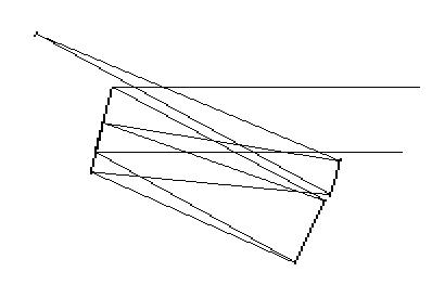
Fig. 3: The ray path of the three-mirror double-pass TCT.
Fig. 4 shows the spot diagram for a three-mirror system with 145mm circular aperture and 1400mm focal length (focal ratio F/9.7). The 200mm convex primary mirror (reflections #1 and #3) has a focal length of -12500mm. The concave paraboloidal mirror for reflection #2 has a diameter of 150mm and a focal length of 1700mm. For reflection #4 a concave sphere with 100mm diameter and 2100mm focal length is used. The mirror distances are 515mm and 525mm respectively. The image plane is located 730mm behind the last reflection and is tilted by 3.7 degree. There is an image distortion of less than 0.7 percent.

Fig. 4: Spot diagram of a 145/1400 three-mirror double-pass TCT for 0.5 degree field of view. The scale is two Airy disk diameters.
Fig. 5 shows other compact three-mirror TCT designs which may be important for specific applications. In the frame of these general concepts, selected system properties like image plane tilt, image distortion, etc., can be optimized almost perfectly, but it seems, that the practical importance of the three-mirror systems is minor compared to the all-spherical two mirror telescope.
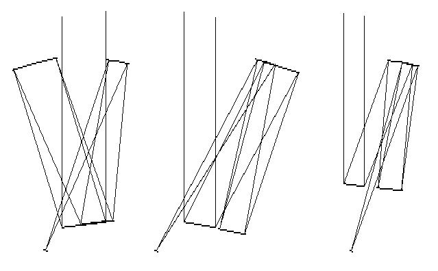
Fig. 5: Other possible configurations of the three-mirror double path TCT.
All spot diagrams shown in this article were obtained with the TCT software by Dr. J. Sasian, Tucson, AZ. This program including the configuration files for the examples introduced in this article can be downloaded from ref. [10].
For his cooperation I would like to thank Dr. J. Pudenz, Jena, Germany. He derived formulae for the direct calculation of the general system parameters. Last but not least I would like to thank Dr. M. Nitschke, Dresden, Germany and D. Stevick, Wellsburg, WV, who contributed to the discussion of the double-pass telescope and helped to verify the novelty of this idea.
Commercial use of the introduced TCT designs is protected by patents. Nevertheless, amateurs are encouraged to make these systems for personal use to get a high quality view into the night sky with a low budget telescope.
| example 1 | example 2 | |
| system parameters | ||
| aperture diameter [mm] | 200 | 145 |
| focal length [mm] | 2300 | 1400 |
| focal ratio | F / 11.5 | F / 9.7 |
| main tube length [mm] | approx. 1200 | approx. 600 |
| primary mirror | ||
| shape | convex spherical | convex spherical |
| disk diameter [mm] | 300 | 200 |
| focal length [mm] | - 8100 | - 12500 |
| tilt [deg.] | 8.0 * | 14.5 * |
| secondary mirror | ||
| shape | concave spherical | concave paraboloidal |
| disk diameter [mm] | 275 | 150 |
| focal length [mm] | 2570 | 1700 |
| tilt [deg.] | 2.8 * | 3.5 |
| dist. from primary [mm] | 1086 | 515 |
| tertiary mirror | ||
| shape | - | concave spherical |
| disk diameter [mm] | - | 100 |
| focal length [mm] | - | 2100 |
| tilt [deg.] | - | 9.3 |
| dist. from primary [mm] | - | 525 |
* with respect to the first reflection at this surface
Curator: Hartmut Frommert
[contact]
[Schiefspiegler Home]
[SEDS]