 The author's 10" Yolo reflector
Erwin Herrig
Geibelstrasse 135
D-09127 Chemnitz
Germany
The author's 10" Yolo reflector
My first Yolo was made with this kind of straining harness which used for the deforming force a lightly loaded flat spring [2] that when applied to the mirror shortened the focal length in one direction while it lengthened it 90 degrees away on the other optical axis. The mirror deformation provided by the harness proved to be stable over various temperatures and for long periods of time and has not needed any adjustment.
It is more elegant, however, to use a mirror figured as a toroid. This can be done simply and will be described below. One should install two pairs of mirror attachment points in the form of drilled grooves or holes in the side of the unground blank. This will leave the face free and available for working. While the mirror is in the deformed state the face is worked with the finest abrasive to a sphere which will return to a 90 degree rotated toroid when released. The complicated procedure of toroidal mirror grinding is reduced to grinding a flawless sphere into a strained blank. The grinding polishing and figuring are well covered in the literature [3] [4] [5].
 fig. 1: Fixture with holes in mirror
Figure 1 shows the assembled fixture with the strained mirror disk. It displays a 6" mirror blank out of Duran (1). The mirror fixture frame for smaller disks can be constructed with correspondingly smaller dimensions.
 fig. 2: Individual parts of the fixture
Figure 2 shows all of the individual parts of the fixture. The tensioning ring (2) is made from strip steel, 3 to 4 mm by 20 mm, or 4 to 5 mm by 30 mm according to size of the mirror. Weld two short cylinders of 10 to 16 mm diameter steel to the ring, that have threaded holes to accommodate both studs (pins) (3) M5 M6. At exactly 90 degrees around the ring, as pictured, weld the two 2 to 3 mm thick metal plates that transfer the deforming force.
The holes for the tension screws must have sufficient clearance and like the small holes for the pressure transmission pins they must be exactly at a 90 degree angle to the threaded hole in the cylinders. The short force transmission bolts (4), of 5 to 8 mm diameter, are secured to the force transmission metal plates (5) and (6) by way of slit shaped holes. They consist of cap screws (3-4 mm size) preferably made out of brass, whose heads by means of soft solder are sized to the correct diameter and depth to snugly fit the holes in the mirror disk. This is done most simply by means of a small aluminum mold. The soft solder assures a uniform and relatively even pressure on the holes in the glass body. In smaller holes in the glass body, if necessary, the diameter of the screw heads can be reduced slightly.
For the 2 to 3 mm thick side force plates (5) and (6), aluminum or brass plate can be used, and for the force transfer plates (7), stainless steel or hard aluminum can be used. The support stud (8) of 1.2 to 2 mm diameter consists of hard brass or steel. The holes in the force transfer plates (7), that receives the support stud (8), should be at least 1 mm larger than the stud diameter. This applies also to the holes of both holding screws (3 mm) (9). The fixture is to be constructed so, that the ring itself is 4 to 6 mm removed from the working face of the glass. The locating screws (4 mm) (10) should be adjusted with a few tenths millimeter clearance to the side force plates (6).
In a simplified variation of the warping fixture , the warping force is directed straight over the side plate (11) at the back edge of the mirror. With this arrangement four of the holes in the mirror as well as the side force plates (6) are eliminated. The force transfer plates (7) are then replaced by plate (12).
In making the warping fixture it is possible to make changes that pertain to your own technical capability and shop conditions. For example the coil spring can be replaced by a flat spring. One can also appropriately, replace one of the coil springs with a simple bushing. The result is that the compliance of the warping ring is turned off on one side. Numerous other variations are possible; only the underlying principle must be preserved. The spring load (force per deflection) should be constant at around 2 to 5 kp/mm.* By replacing a spring, this value would be halved.
The simplified version of the warping fixture can, without noticeable loss in control, change the focal line separation from less than 150 mm to more than 3 meters. When in the indicated range one should not become overly fussy, because by being slightly on the strong side one obtains a better toroidal mirror. In large mirrors, however, it is preferred to introduce the deflecting force at the holes in the side using the more complete fixture.
The preparation of the secondary disk begins with the measurement {control} of its thickness. If the thickness difference is greater than a few tenths millimeter at different places one should through coarse grinding even it up. Next one should make the four and/or eight holes (5 to 8 mm in diameter) as exactly as possible at the 30 degree (60 degrees) angles . The holes should be 2 to 3 mm deep.
It is preferred, that the bending force be applied from beyond the midline of the mirror, i.e., the pulling from below the midline and the pushing from above the midline and therefore the holes should be offset accordingly. At the same time the allowed tolerances should be + /- 10%. The exact placement of the holes around the disk at 90 degrees is most important and also the same offset for each pair of holes. By adjusting the slotted metal side plates however it is possible to achieve a balance in the force. By means of a diamond drill, the holes can quickly be made in the glass, but they can also be easily drilled in 8 to 15 minutes with a soft steel or copper bolt (best if annealed) and carborundum 80X -150X with water in a drill press.
After grinding the unstrained mirror to a sphere (carbo 600-800X) the process can be interrupted. The radius should still be few centimeters longer than the desired radius.
Next put a quick shine on the mirror. This can be done by just rubbing in some graphite or molybdenum disulfide. It is best, however, to put a flash polish on the mirror by hand using a paper lap. After polishing a short time the surface will shine enough, that after putting the disk under strain the focal plane separation can be observed by adjusting the tension springs.
For that purpose one needs only an artificial star {pin hole} and a long to middle focal length eyepiece as well as a simple arrangement for measuring the separation between the two foci of the mirror. There is nothing special about the level of polish as well as the accuracy needed to measure the separation of the line foci. My experience indicates that the focal line interval should be adjusted on the high side, say by +5 to 10%. The turning of the tension spring screw is a good measure of the focal line separation and is almost proportional.
Now finish grinding with the finest abrasive. The toroidal surface will again be returned to its spherical figure. If you are at the required curvature {I assume this is the mean radius between the two design radii} you can begin the usual final polishing process. As soon as the first measurement is possible, one can check the focal line separation in the unstrained condition and if necessary correct by changing the deformation.
The additional steps are simply to figure a sphere using the well known null with the knife edge test while maintaining the required focal line interval. To ensure that the actual state of deformation is not affected, the final polishing should be done by applying minimal pressure.
If the desired focal separation is not entirely reached, however, and otherwise the surface form is flawless, one only has to adjust the Yolo mirror tilt angles accordingly. An intrusion of the toroidal secondary into the entrance aperture of up to 20% does not influence the image quality (contrast) in the slightest. This can be easily verified in the finished Yolo with the aid of a paper mask. Too large of a focal line separation leads to increasing the mirror angles and if carried to extremes will be even more injurious to the image quality.
The accuracy attainable without additional figuring of the mirror surface is better than 1/10 wave, peak to valley, and is sufficient in all cases for the usually displayed Yolo. The quality can easily be verified with the null test method in [6,7]. It will take a perfectionist, that will zone figure using the means indicated in [6] and [7]. After my experiences with various figured toroidal mirrors from 115 to 155 mm diameter and focal line separations of up to 300 mm, I can say there have been no serious pitfalls.
With this publication, I would like to make available and distribute to the amateur telescope maker the technique to construct the excellent Yolo optics design. A beginning glass worker using the warping fixture, and without hand figuring a toroid, can produce a flawless Yolo telescope.
 fig. 3: 10" Yolo reflector, uncovered
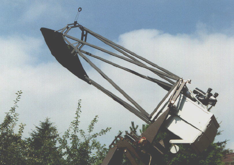
Figure 3 is an example of the successful application of a pre-formed toroidal mirror, and shows my handmade 10" Yolo. It has only a 3 meter focal length and by inserting the 6" secondary, around 28 mm, into the incoming light path its overall length was held to a relatively short 2 meters (without the light stop and screen in place).
 fig. 4: 10" Yolo Reflector, completely covered
While observing, a cloth screen added to the grid tube of the telescope serves as additional protection against convective air flow (fig. 4). As needed, an adjustable aperture stop in the mirror housing allows the opening to be 8", 6" or 4.5".
 fig. 6
 fig. 7
Curator: Hartmut Frommert
[contact]
[Schiefspiegler Home]
[SEDS]